Data flow
The UmTRX high-level architecture can be seen below.
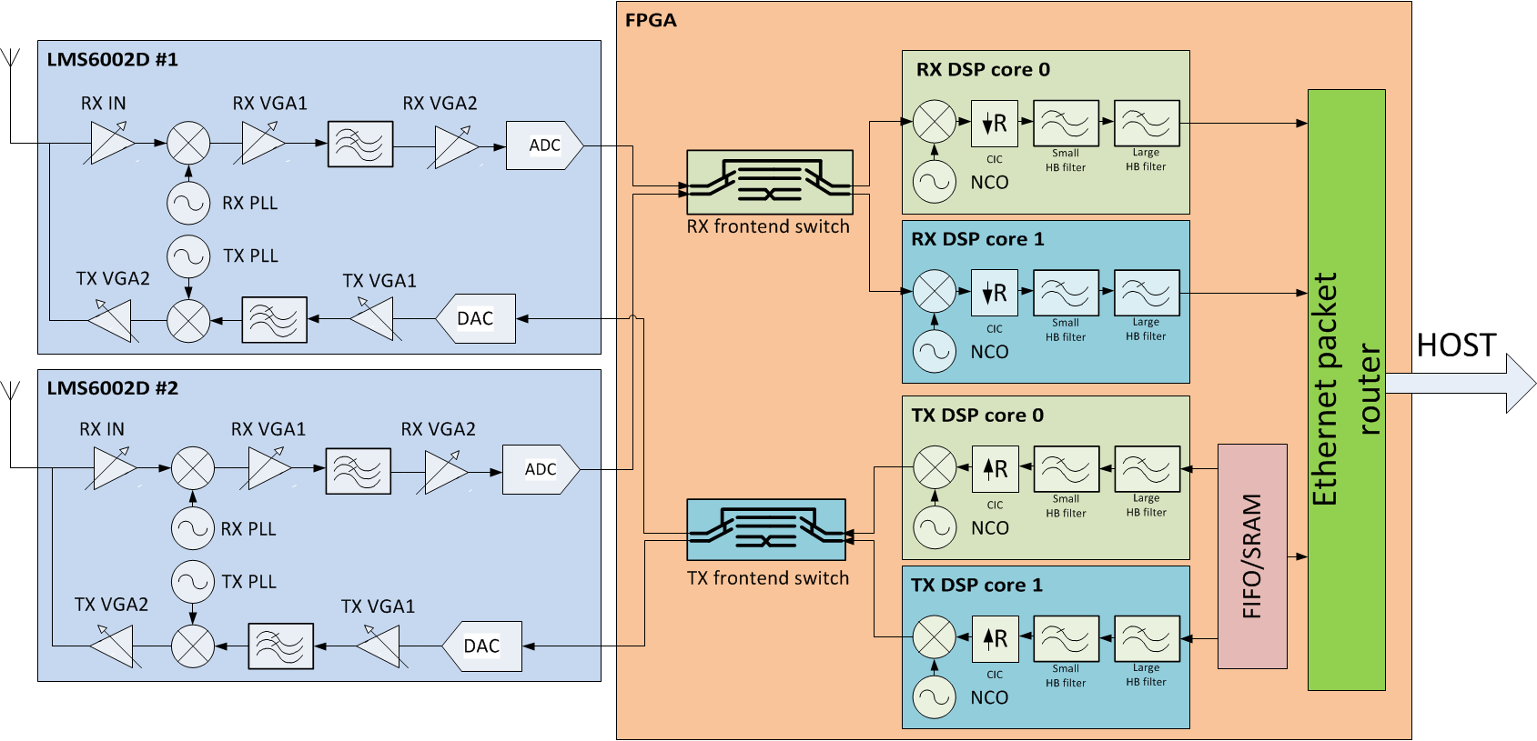
Click on the image to view a larger version of the diagram.
Peripherals and buses
Peripheral | Buses |
|---|---|
| 2x LMS6002D | 2x SPI 2x 12-bit parallel data Rx 2x 12-bit parallel data Tx |
| TCXO DAC | SPI |
| Flash | SPI |
| GPS | UART 1pps |
| Debug UART | UART / Mini-USB |
| SRAM | 21-bit parallel address 36-bit parallel data 9-bit parallel control |
| 1 GbE PHY | 8-bit parallel Tx 8-bit parallel Rx parallel control 2x GPIO (LEDs) |
| Temperature sensor | 2x GPIO (FAN_ON and OVERHEAT signals) |
| Buttons | 1x GPIO (SAFE) FPGA RESET |
| LEDs | 5x GPIO FPGA DONE |
| Debug FPGA connector | 32-bit parallel bus |
| Mezzanine connector | 7x GPIO |
Stacking
Multiple boards can be stacked using a standard gigabit Ethernet switch, with the option of sharing a common — onboard GPS synchronized — or external clock source.